
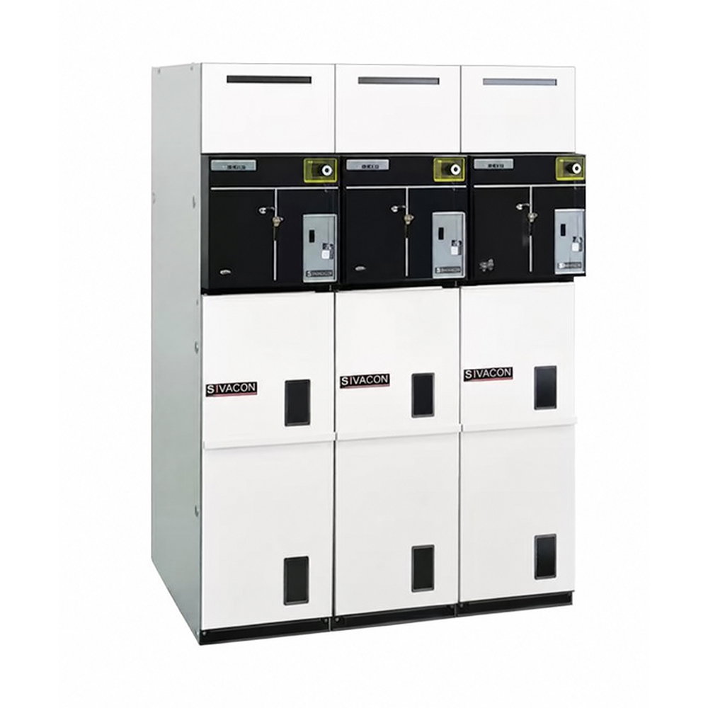
The SM6 switchgear is designed for indoor installation, with actual dimensions of:
Width: 375 – 750mm
Height: 1600 – 2050mm
Depth: 840mm (floor-standing dimensions)
It is suitable for installation in distribution rooms or compact substations, with cable connection from the front side.
All control functions are centralized on the front operating panel, simplifying operation. The switchgear can be equipped with accessories such as relays, coils, and instrument transformers.
Ambient Temperature
1.Not exceeding +40°C
2.Average temperature over 24 hours not exceeding +35°C
3.Not lower than -25°C
Altitude
1.For 12kV products: not exceeding 2000m
2.For 24kV products: not exceeding 1000m
3.If exceeding the above limits, derating is required (please consult our company)
Sunlight Exposure
Direct sunlight is not permitted
Environmental Pollution
Free from heavy dust, smoke, corrosive substances, flammable gases, steam, or salt fog
Humidity
1.Average relative humidity over 24 hours not exceeding 95%
2.Average relative humidity over 1 month not exceeding 90%
3.Average vapor pressure over 24 hours not exceeding 2.2kPa
4.Average vapor pressure over 1 month not exceeding 1.8kPa
Under these conditions, the possibility of condensation on the equipment is low. If high humidity is accompanied by significant temperature variations, condensation may occur. To prevent insulation damage caused by high humidity and condensation, appropriate ventilation facilities and devices should be provided in the building design, in accordance with civil engineering recommendations.
Harsh operating conditions (please consult our company)
Standards
The SM6 switchgear complies with the following standards and specifications:
Chinese GB/T standards: GB/T3906, GB/T11022, GB/T3804
Chinese DL standards: DL/T404, DL/T593
International standards: IEC 62271-200, 62271-1, 62271-105, 62271-100, 62271-102, 60255, 60265
UTE standards: NFC 13.100, 13.200, 64.130, 64.160
EDF standards: HN64-S-41, 64-S-43
Designation Symbols
SM6 cubicle specifications are defined by the following code:
Functional electrical code: IM‑QM‑DM1‑CM, etc.
Rated current: 630‑1250 A
Rated voltage: 7.2‑12‑24 kV
Rated short‑time withstand current: 20 kA / 4 s*
Example:
Cubicle designation IM630‑12‑20
IM: Incoming or outgoing cubicle
630: Rated current 630 A
12: Rated voltage 12 kV
20: Short‑time withstand current 20 kA / 3 s
* These high‑level parameters are optional; please specify in advance if required.
Rated Voltage (kV) | 12 kV | 24 kV | |
Insulation level | |||
50 Hz / 1 min (kV r.m.s.) | To earth | 42 | 65* |
Across isolating distance | 48 | 79* | |
1.2/50 µs (kV peak) | To earth | 95 | 125 |
Across isolating distance | 110 | 145 | |
Breaking capacity | |||
No load transformer (A) | 16 | ||
No load cable (A) | 25 | ||
Short time withstand current & duration (kA/s) | 25 kA 1 s 20 kA 3 s 20 kA 4 s* | 20 kA 1 s | |
5 % rated load breaking current (A) | 31.5 | ||
Closing & Breaking Capacity | E3 | ||
Rated active load breaking current | 630A | ||
Rated loop breaking current | 630A | ||
Rated short circuit making current (kA) | 50 kA, 63 kA | 50 kA | |
Short time withstand for earthing switch | 12.5 kA /1 s or 20 kA /1 s* | ||
* These high‑level parameters are optional; please specify in advance if required.
Maximum breaking capacity | ||
Rated Voltage (kV) | 12 | 24 |
IM, IMC, IMB, NSM-C | 630A | |
QM, QMC | 31.5kA | |
DM1-A, DM1-D | 25kA | |
Life | Mechanical Life | Electrical Life |
IM, IMC, IMB QM,QMC | IEC 60265 load break switch – 5,000 operations | IEC 60265 200 rated active load break operations Class E3 |
DM1-A, DM1-D | IEC 62271-100 10,000 operations | IEC 62271-100 40 breaks at 12.5kA 25 breaks at 20kA 20 breaks at 25kA 10,000 breaks at In, pf=0.7 |
According to IEC 62271-200 and GB/T 3906:
Service continuity level: LSC2A
Partition class: PI
Protection degree: IP4X*
** Transfer‑current breaking: 3 times in accordance with IEC 60420 & GB 16926.
l 1750 A for 12 kV
l 1400 A for 24 kV
Electromagnetic Compatibility
Relays: 4kV withstand voltage according to IEC 60801.4
Shielded room:
l Electric field: -100MHz, attenuation 40dB -200MHz, attenuation 20dB
l Magnetic field: below 30MHz, attenuation 20dB
Temperature
l Storage: -40°C to 70°C
l Operation: -25°C to 40°C
l Below -25°C, please contact us
l If more mechanical endurance cycles are required, please contact u
Load Break Switch / Combined Apparatus Unit Structure
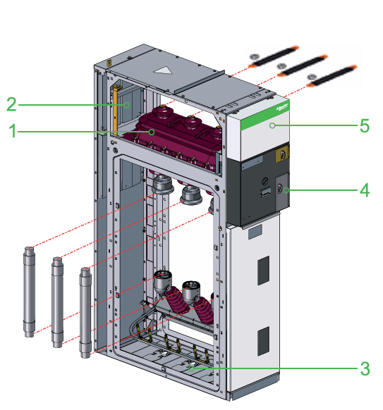
1.Switch Compartment: The load break switch, disconnector, or earthing switch is sealed in a gas-filled chamber containing SF6 gas, conforming to the "sealed pressure system" standard. The compartment houses a three-position load break switch, with an epoxy resin cast enclosure using SF6 gas as the insulating medium. An observation window is provided on the housing. A gas pressure gauge can be installed upon customer request.
2.Busbar Compartment: All busbars are located on the same horizontal plane. The cabinet can be extended to both sides, with simple interconnection between cabinets.
3.Cable Compartment: Cables are connected from the front side, allowing easy connection to the switch and earthing switch terminals. When used for transformer protection, an earthing switch is also installed on the lower side of the fuses in this compartment.
4.Operating Mechanism Compartment: Houses the operating mechanism for closing, opening, or earthing operations, with position indication. An electric operating mechanism can also be installed.
5.Low Voltage Compartment: Contains low-voltage fuses, protective relays, terminal blocks, etc. If the compartment space is insufficient, an extended low-voltage compartment can be added on top of the cabinet.
SF6 Circuit Breaker Unit Structure
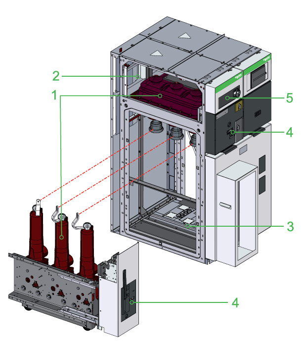
1.Switch Compartment: The load break switch, disconnector, or earthing switch is sealed in a gas-filled chamber containing SF6 gas, conforming to the "sealed pressure system" standard. The compartment houses a three-position load break switch, with an epoxy resin cast enclosure using SF6 gas as the insulating medium. An observation window is provided on the housing. A gas pressure gauge can be installed upon customer request.
2.Busbar Compartment: All busbars are located on the same horizontal plane. The cabinet can be extended to both sides, with simple interconnection between cabinets.
3.Cable Compartment: Front-side operation allows easy connection to the circuit breaker. Current transformers and voltage transformers can be installed if required. Two types of circuit breakers can be accommodated in this compartment:
SFset: Equipped with self-powered protection devices and special sensors (no auxiliary power supply required).
SF1: Equipped with integrated protection relays and standard sensors, requiring an auxiliary power supply.
4.Operating Mechanism Compartment: Houses the operating mechanism for closing, opening, or earthing operations, with position indication. An electric operating mechanism can also be installed.
5.Low Voltage Compartment: Contains low-voltage fuses, protective relays, terminal blocks, etc. If the compartment space is insufficient, an extended low-voltage compartment can be added on top of the cabinet.

 +86 139 6879 9444
 +86(0)577-27885177
 +86(0)577-27885155
 No.555 Chezhan Road, Liushi Town, Yueqing, Wenzhou, Zhejiang Province, China 325604


 wzebl@wzebl.com


