

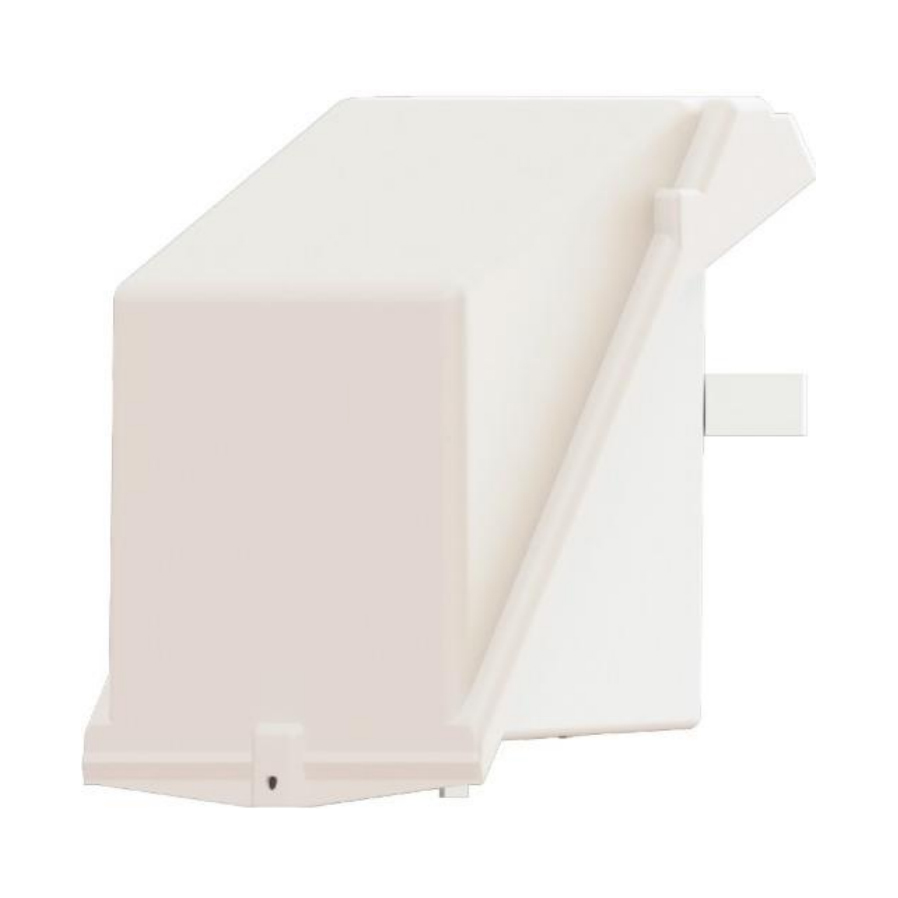
◆ Temperature:-40℃~+70℃
◆ Humidity:100%
◆ Altitude:≤2000m
◆ Wind speed:≤40m/s·H
Note:No fire,no explosion hazards,no chemical corrosion and recurrent severe vibration.
◆ 1.Incoming wiring clamp 5.Digital trip unit
2.Incoming wiring hole 6.Load indicator trip indication
3.Arc chute grid 7.Position indicator
4.Operation mechanism 8.Operation handle
Users can connect the transformer's low-voltage side or other four-phase(3P+N)power sources as the incoming power supply for this circuit breaker.Additionally,its unique design eliminates the need
for users to crimp lugs before connection(as shown on figure
2). Additionally,the wiring clamps below it serve as outgoing and phase sequence must be ensured during connection.
2.Incoming wiring hole
Users can insert cables into the circuit breaker at this location.Similar to point 1,its lower section is designed for outgoing connections.
3. Arc chute grid
This grid is designed to extinguish arcs during circuit breaker operation.Users can replace this component based on the current condition of the grid.
4.Operation mechanism
This area houses the circuit breaker's operating mechanism.Designed as a spring- charged closing mechanism with a trip-free release,it can be operated via a floor- mounted handle.
5.Digital trip unit
Digital Trip Unit,distinct from traditional thermal trip units or fixed-function PCB hardware trip units,features embedded current transformers with phase-to- neutral voltage supply.It complies with the trip response time and accumulated overload response time specified in the HN63-S11 standard.The capacity is configurable to 50,100,or 160 kVA as required.
6.Load indicator trip indication
The orange component will drop down when the accumulated load time is reached (indicated by Component 6 rotating clockwise past the 0 position)and Component 10 is in the configuration shown.This action will internally trigger the circuit breaker to trip.
7.Position indicator
The green component protrudes minimally at the bottom when in the closed position. When in the open position,a significantly longer section becomes visible.
8.Operation handle
This handle connects to the floor-mounted operating handle.During installation, users must secure the linkage pin with a split pin.Downward movement initiates tripping/spring-charging,while upward movement performs the closing operation.
9.Load trip enable/disable handle
This handle enables or disables the trip function of the load indicator.
Downward position:
Operate the 9#Operation Handle downward to charge the mechanism,then upward to close the circuit breaker.During this motion,the 7#Load Indicator Trip Indication resets. If the circuit breaker detects overload,the 6#Load Indicator activates When its pointer rotates clockwise past the 0 position,the breaker trips. Inward position:
The load indicator continues monitoring but disables tripping.
Installation diagram
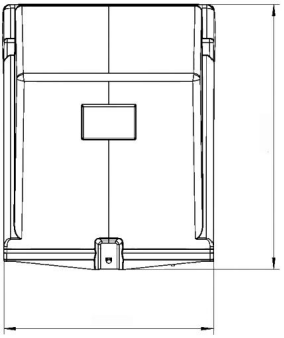
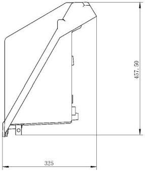
Figure 4shows the installation diagram.The floor- mounted operating handle connects to the circuit breaker via a standard iron pipe.The illustrated utility pole is circular;if a square utility pole is used, this must be specified in the installation notes.

 +86 139 6879 9444
 +86(0)577-27885177
 +86(0)577-27885155
 No.555 Chezhan Road, Liushi Town, Yueqing, Wenzhou, Zhejiang Province, China 325604


 wzebl@wzebl.com


